
Tutorials,Industries
Topographic LiDAR Workflow: Create DTM, Contours, and Hillshade from Aerial Data
A topographic LiDAR workflow for turning aerial scans into DTM, contours, hillshade, slope maps, and DXF-ready deliverables
No credit card required • 50 hectares included
Topographic mapping teams use aerial LiDAR to move from raw point clouds to bare-earth terrain models, contour lines, slope maps, hillshade, and CAD-ready deliverables. With the right workflow, you can classify ground, generate DTM outputs, extract features, and hand off DXF or GIS files without weeks of manual cleanup.
When buyers search for topographic LiDAR, they usually need a repeatable way to turn aerial data into survey-ready terrain outputs, not just a viewer. The useful workflow starts with ground classification, then moves through DTM generation, contour cleanup, hillshade review, and export handoff for CAD or GIS teams.
What topographic LiDAR should produce before CAD handoff
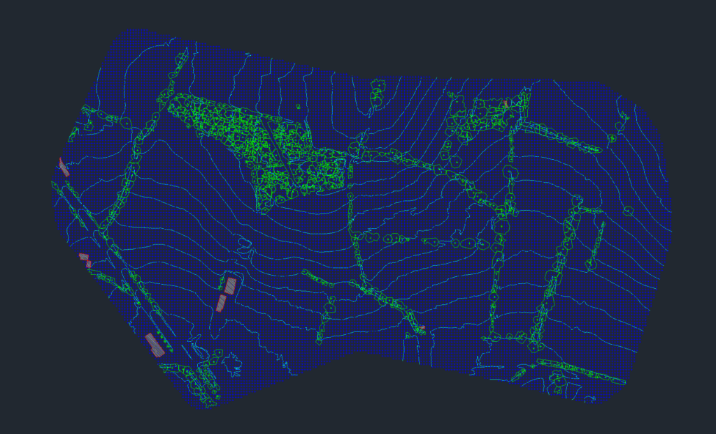
For most survey teams, topographic LiDAR is only valuable when it produces terrain outputs that are ready for review and downstream drafting. A strong workflow should give you bare-earth terrain, visual QA products, and exports that fit the rest of your stack.
- DTM or gridded terrain: a clean bare-earth surface for mapping and analysis
- Contours, hillshade, and slope maps: reviewable terrain products for topo interpretation
- Feature extraction: optional building footprints, breaklines, or related vectors when the job needs them
- CAD and GIS handoff: DXF, TIFF, SHP, GeoJSON, or LAS outputs for the next step
Step 1: Contour Generation
Contour lines represent lines of equal elevation, helping visualize three-dimensional terrain on a two-dimensional plane. Here’s the process:
Data Import & Filtering
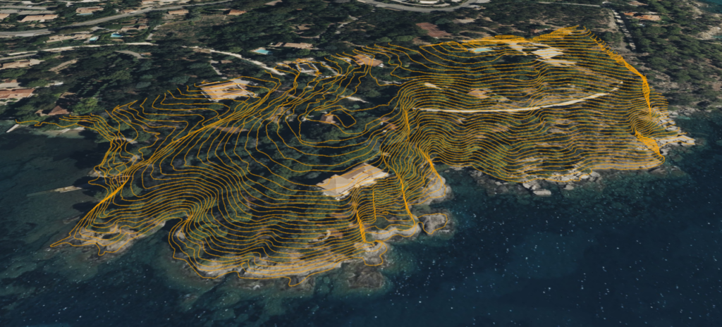
Import the raw LiDAR point cloud into specialized GIS or point cloud processing software. Clean and filter out noise or erroneous data points caused by vehicles, birds, or sensor anomalies.
TIN Creation
Convert filtered LiDAR points into a Triangulated Irregular Network (TIN), which forms a mesh of connected triangles representing the surface.
Contour Extraction
Specify a contour interval (e.g., 1 meter or 5 meters) depending on required detail. Automated algorithms trace along constant elevation values to generate contour lines.
Smoothing & Cleaning
Smooth jagged lines to improve map readability. Remove or adjust contours that are extremely close together if they result from noise.
Industry Use: Accurate contours are critical for construction site planning, hydrological analysis (flood plain studies), and environmental impact assessments.
Step 2: Grid Generation
Grid generation creates a regularly spaced matrix of points representing terrain. It’s useful for volume calculations and slope stability analysis.
01
DEM Creation
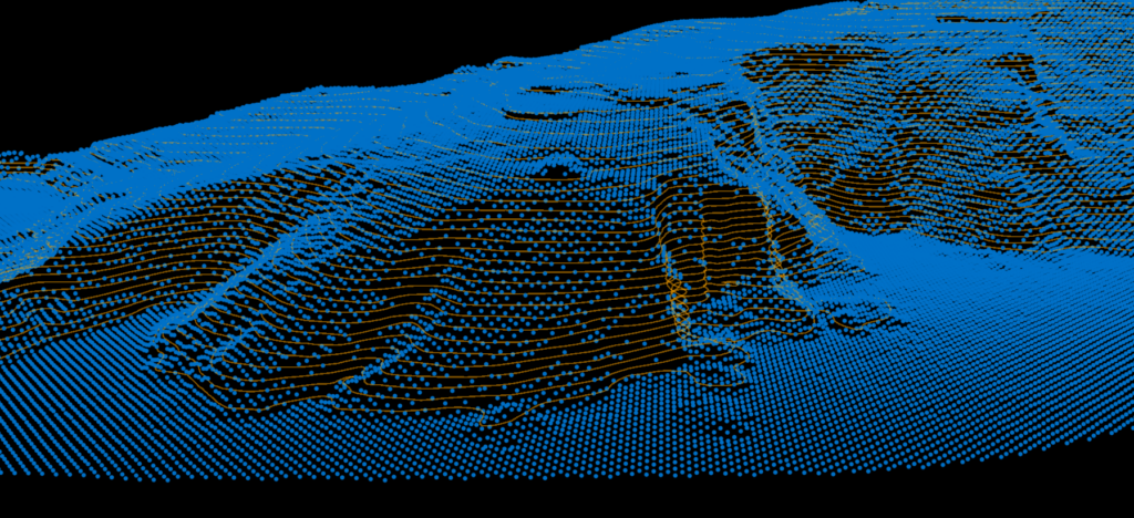
Convert LiDAR data into a Digital Elevation Model (DEM) through interpolation. The DEM is a grid where each cell value represents elevation at that location.
02
Adjust Resolution
Define grid resolution (e.g., 1m x 1m or 5m x 5m). Finer resolution captures more detail but produces larger datasets. Balance resolution with processing overhead.
03
Assign Elevations
Each grid cell is assigned an elevation value through bilinear interpolation of nearby LiDAR points, creating a smooth terrain representation.
Industry Use: DEMs form the foundation of geospatial analyses in urban planning, mining (volume calculations), and infrastructure development.
Step 3: Building Footprint Extraction
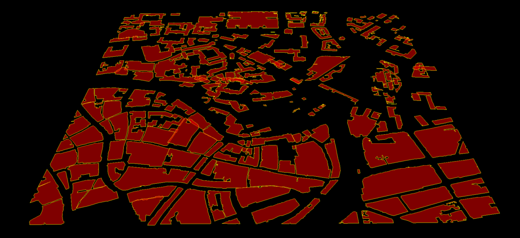
Ground vs. Non-Ground Classification: Classify points using algorithms like cloth simulation filtering or progressive triangulation.
Height Thresholding: Apply thresholds (e.g., anything above 2 meters) to identify buildings or tall vegetation.
Shape Detection: Look for planar surfaces or rectangular outlines. Automated algorithms segment data and detect polygonal rooftop shapes.
Post-Processing: Refine footprints by removing noise polygons and merging adjacent polygons belonging to the same structure.
Industry Use: Building footprints are indispensable for city planning, insurance risk assessment, emergency response planning, and architectural design.
Step 4: Tree Detection
Distinguishing vegetation from other non-ground points is crucial for environmental monitoring, forestry management, and urban planning.
Identify Vegetation Points: After separating ground and non-ground points, classify vegetation based on reflectance properties, height, and shape. Multi-return LiDAR helps identify foliage density.
Filtering & Smoothing: Eliminate outliers like utility poles that don’t fit vegetation profiles. Apply smoothing algorithms to group contiguous vegetation points.
Segmentation: Trees appear as point clusters. Automated cluster analysis groups these points and separates individual trees based on vertical distribution.
Step 5: Tree Crown Delineation
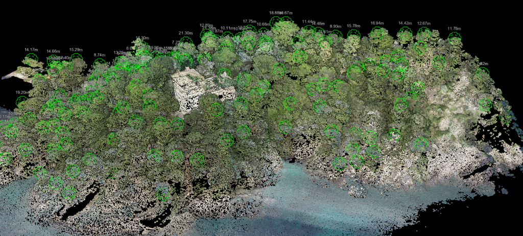
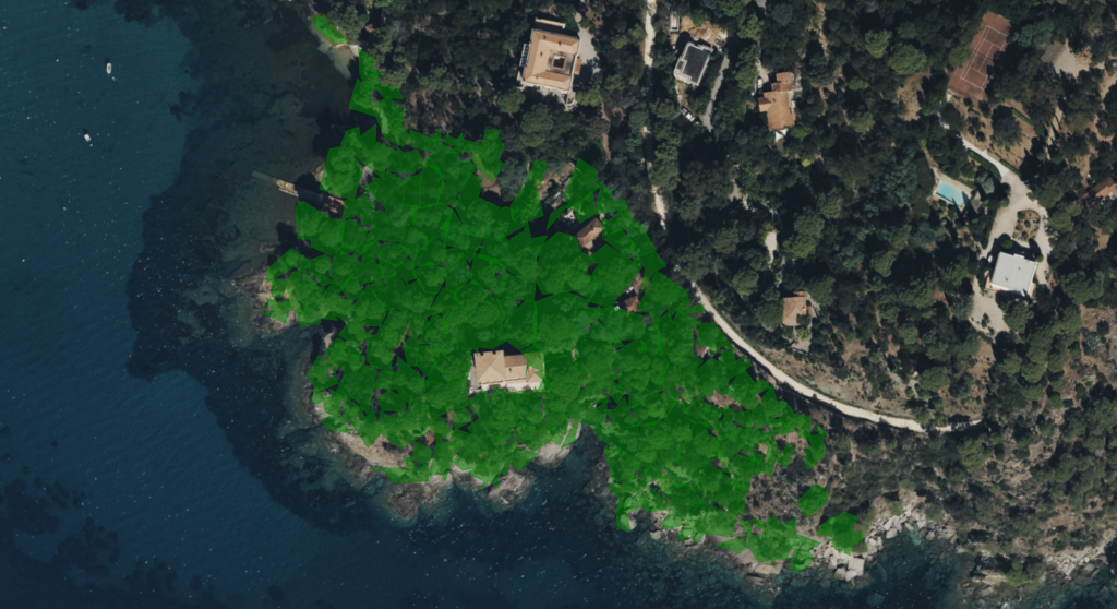
Canopy Height Model (CHM): Subtract ground elevation (DEM) from top-of-canopy elevation to obtain a CHM representing vegetation height above ground.
Local Maxima Detection: Identify the highest points (peaks) within each crown using local maxima filters. Each maximum corresponds to a separate tree.
Watershed Algorithms: Use local maxima as seed points for region-growing segmentation to delineate crown boundaries.
Validation: Merge over-segmented crowns and separate large clusters with multiple peaks.
Industry Use: Detailed tree crown data is vital for forestry management (inventory and health assessment), utility corridor management (preventing outages), and environmental habitat studies.
Step 6: Export to DXF
To integrate topographic data with CAD software, export the processed information in a compatible format.
Data Simplification
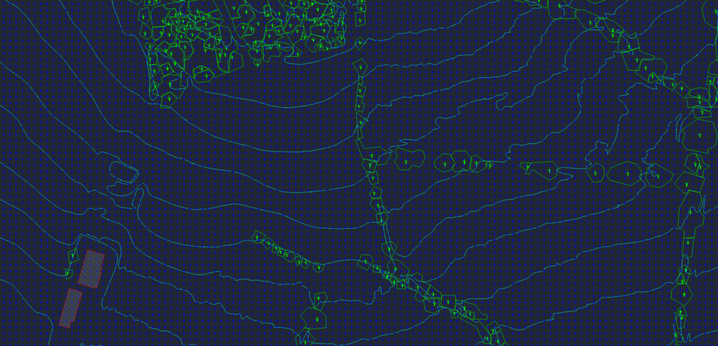
Before exporting, simplify complex polygons (building footprints, tree crowns) to reduce file size and maintain manageable detail.
Layer Organization
Assign different layers for contours, building footprints, tree outlines, and other feature classes. This allows easy manipulation and visibility control in CAD software.
Export Settings
Select DXF as the file format. Double-check coordinate system settings to ensure consistency across platforms.
Quality Assurance
Open the DXF file in CAD software to confirm proper layer segmentation, alignment, and scale.
Why Automation Matters
Implementing automated techniques across all steps dramatically reduces manual labor. Traditional field surveying and manual classification are time-consuming and error-prone. Automation offers
Speed
Automated algorithms process massive LiDAR datasets far more quickly than manual methods.
Consistency
Defined algorithms apply the same rules across the entire dataset, minimizing human bias or oversight.
Scalability
As drone technology improves, vast areas can be surveyed quickly, making automation essential for large datasets.
Related Industry Applications
Infrastructure
• Bridge & Road Inspection
• Powerline Extraction
• Pole Extraction
• Solar Farm Site Assessment
• Construction
• Real Estate & Development
Natural Resources
• Forest Inventory
• Forest Guide
• Vegetation Management
Geospatial
• Surveying
• Terrain Mapping
• Archaeology
Automate Your Topographic Mapping
From contour generation to tree crown delineation, Lidarvisor automates the entire topographic mapping workflow. Upload your LiDAR data and get professional results in minutes, not weeks.